MCP23017 Breakout board for connection to HD44780 character LCD
MCP23017 Breakout board for connection to HD44780 character LCD (and other uses)
Intrigued by the simplicity of setting up an MCP23017 I2C chip and easily getting 16 General Purpose input/output pins, my mind turned to using the chip to make an I2C connected HD44780 character LCD device. The breakout board has proved useful for other purposes as well.
In 8 bit mode an HD44780 based LCD needs 8 data connections, and 3 control connections (Enable, R/W, and RS) leaving 5 GPIO lines for other purposes. I used one of the lines for controlling the LED back light on the LCD - the MCP23017 can provide upto 25mA output current which was more than enough for an adequate backlight.
In 4 bit mode only 4 data and 3 control lines are needed leaving 9 lines for other uses. However, the I2C bus running as the usual 100KHz is not the fastest bus, and driving the LCD in 4 bit mode needs twice as many I2C write transactions for each byte written to the display. I believe some commercially available I2C adapters for LCDs use the MCP23017 connected to the LCD for 4 bit mode.
The Circuit
The circuit is pretty simple. Each 8 bit port of the chip is brought out to the edge of the board - to header pins for GPIOA, and to a header socket for GPIOB. The 16 pin header socket is provided to be able to connect an LCD display with a standard 14 pin straight connector, along with the LCD backlight anode/kathode bought out to pins 15/16. The Anode is fed from the output of GPIOA line 4. GPIOA lines 5, 6 and 7 are patched to LCD RS, R/W, Enable lines respectively. The LCD lines 1 and 2, 0v and 5v, are patched to the I2C bus connector pins which provide ground, 5v SDA and SCL lines.
GPIOA lines 0, 1, 2 and 3 are free for any other use, e.g. connecting a sounder to provide an alarm function, or to use as inputs for connecting a few switches.
*** UPDATE *** The contrast pin 3, Vee, is unconnected, as the LCD I used had fixed contrast. There is enough spare space to install whatever contrast connection/adjustment is needed for another LCD module. Usually a potentiometer between V+ and 0v with the wiper going to Vee. However some LCDs can work with a simple resistor between Vee and 0v, choose you fixed resistor for the contrast needed.
The I2C connection is to a 4 way header pin connector - right angled header pins in my version.
The address lines are pulled high by default, giving an I2C address of hex 27. 3 pairs of header pins are provided between the address pins and ground so that any combination of address pins can be selected to give any address between hex 20 and hex 27 ...
   A2  A1  A0   Hex address
   J   J   J    20  all jumpers fitted
   J   J   -    21
   J   -   J    22
   J   -   -    23
   .....
   -   -   J    26
   -   -   -    27  no jumpers
If you want to set a fixed address simply wire the Address pins as necessary to 0v and V+ and omit the jumper setup.
The RESET line is tied high via a resistor, and connected to a header pin. If required a reset switch, to short the pin to ground, can be connected.
INTA and INTB are simply brought out to header pins and are available.
Of course the board does not have to be used for driving an LCD module, it can be used for other purposes. I made up a simple R2R DAC ladder on stripboard with right angled headerpins to connect to the GPIOB header socket and the ground on socket pin 16. This made a very simple 8 bit DAC.
This board does not have pull-up resistors on the 2 I2C lines SDA and SCL. In my case the pull-up resistors were on the board with 3.3v to 5v converters. In you need I2C pull-up resistors, there is space on the board.
Circuit Diagram
Stripboard layout - top view and trackside view
I used a piece of 0.1 inch stripboard 25 by 16 holes. Apologies for the low contrast images, they are scans of pencil drawings. (1)


Annotated Photo of breakout board
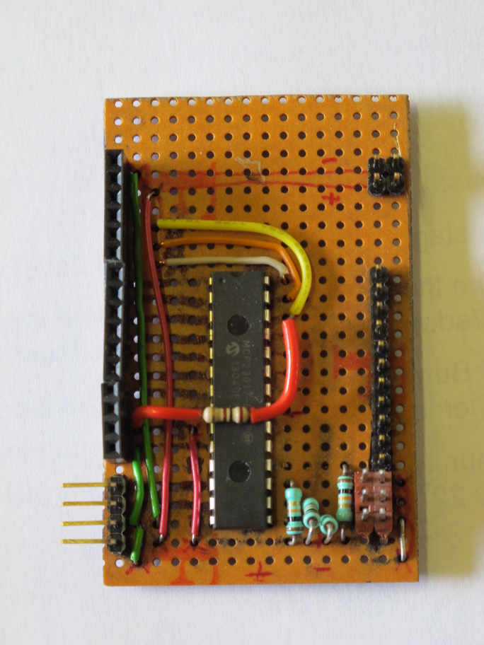
N.B. Annotations to be done! (1)
PCB Design *** UPDATE ***
Guillaume Pascal has used the info on this page as inspiration to create a PCB for this break-out board, and has kindly made his design available. He has used KiCAD software to create a neat circuit diagram and a very small and compact PCB design ...
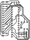
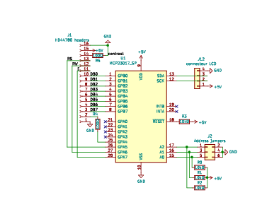
The KiCad files are here in a zip archive ...
http://franjam.org.uk/electronics/MCP23017-LCD_kicad.zip
Software
I've written software for Linux to drive the MCP23017, which uses standard I2C Linux kernel devices to read and write to the MCP23017 registers. This was developed and tested on a RaspberryPI device, but should be Linux generic.
Refs to Software to be added here - email me
WARNING: the RaspberryPI I2C lines were connected through bi-directional 3.3v to 5v converters, and power was taken from the 5v line. This provides the 5v needed for the LCD module.
If the board is not used with an LCD module, then the MCP23017 will work from 3.3v and connect direct to the RaspberryPI lines. In this case, DON'T connect voltages higher than 3.3V to the pins of the MCP23017 chip, or you could damage it.
(1) One day I'll get to grips with graphics software for doing this stuff.
Jim Jackson <jj@franjam.org.uk> Wed May 15 20:52:58 BST 2013
This document was generated using AFT v5.095